Zero Crossing Detector Circuit Using Optocoupler / I want to use it in the electronic load controller (elc) to dump excess power to the heater.
Zero Crossing Detector Circuit Using Optocoupler / I want to use it in the electronic load controller (elc) to dump excess power to the heater.. This video is about optocoupler 4n25. Zero cross detector is kind of voltage comparators used to detect the change in waveform. I want to use it in the electronic load controller (elc) to dump excess power to the heater. Zero cross detector circuit working and simulation using proteus. My supply voltage is 220 v, 50 hz and my oscilloscope is showing 100 hz freq (freq of o/p signal).
You can also use ltspice to 'inject' noise into the circuit to see how it deals with nearby noise injection from things like microwave ovens, furnace igniters and. Review ac relay circuits optocouplers triacs. (the unsung heroes of modern electronics design) rod elliott (esp). My supply voltage is 220 v, 50 hz and my oscilloscope is showing 100 hz freq (freq of o/p signal). I want to use it in the electronic load controller (elc) to dump excess power to the heater.
AC Motor Speed Controller Circuit Using AT89C51 from bestengineeringprojects.com Start date nov 19, 2003. Zero cross detector circuit working and simulation using proteus. A zero crossing detector does not require full wave rectification. Zero cross detector circuit | working and simulation using proteus. When we control the ac light through microcontroller then it's necessary to detect zero cross for effectively apply pwm pulse to ac light. There are many type of ways to create zero cross detectors from which the op amp based method is very useful as it provide many edges over their competitive methods. I have a series resistor which is valued at 33kilo ohms 5watts, in series with. I am getting the parts tomorrow for cmartinez zero cross detection circuit only because it seems to have less of them.
My circuit is not yet complete, but am i correct in saying that the h11aa1 will detect a time around the crossing rather than the peaks?
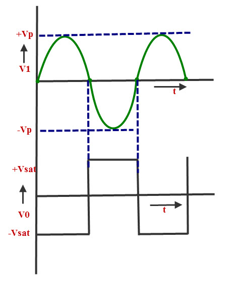
Zero crossing detectors widely find applications in electronics circuits mainly for switching purpose and in phase locked loop. I need a zero crossing detector for a project i'm working on, and came across this design mentioned here on eevblog. A zero crossing detector does not require full wave rectification. .i can use the edges to detect zero crossing, so a diode follwed by a constant current source (2 pnps) and then the optocoupler diode might do. (the unsung heroes of modern electronics design) rod elliott (esp). Zero crossing detector basically detect zero voltage points and inform the controller or controller circuit. Zero cross detector is kind of voltage comparators used to detect the change in waveform. It can also be named as the sine to square wave converter. These systems also require correct measurements that are not affected from distortions on the grid. The circuit must contain a opto coupler which can welcome to our site! I have got an output as shown in fig. All i did was remove diodes d1 and d4 for the former, and d2 and d3. Zero cross detector circuit working and simulation using proteus.
Hi, i am looking for a circuit/ ic which can provide a zero crossing output (square wave ideally). When the zero cross occurs, an interrupt will occur if the zcd. Zero crossing detector circuit is similar to a comparator but one of the input pins connects with a ground terminal. The phototriac optocoupler consists of an infrared led optically coupled to a photosensitive triac detector die. We can make it using an opamp, as shown below, however using a opamp.
Zero Crossing Detector Circuit and Its Applications from www.elprocus.com Which is used for zero cross detector. Zero crossing detector circuit is similar to a comparator but one of the input pins connects with a ground terminal. By the way why are you being. We can make it using an opamp, as shown below, however using a opamp. Zero crossing detectors and comparators. At zero crossing of a sine wave, optocoupler turns off and a pulse of vcc magnitude appears at the output. All i did was remove diodes d1 and d4 for the former, and d2 and d3. I have got an output as shown in fig.
.i can use the edges to detect zero crossing, so a diode follwed by a constant current source (2 pnps) and then the optocoupler diode might do.
Also, you wouldn't need now you tell me raschemmel why isn't rectification required as the reverse voltage this optocoupler can handle is just 5v. You can also use ltspice to 'inject' noise into the circuit to see how it deals with nearby noise injection from things like microwave ovens, furnace igniters and. Edaboard.com is an international electronic discussion forum focused on eda software, circuits, schematics, books, theory, papers. (the unsung heroes of modern electronics design) rod elliott (esp). I have got an output as shown in fig. Also, these are used in frequency counters and in phase meters. For this, any one of the inverting/ noninverting comparators can be used as a zero crossing detector. Review ac relay circuits optocouplers triacs. I am getting the parts tomorrow for cmartinez zero cross detection circuit only because it seems to have less of them. When we control the ac light through microcontroller then it's necessary to detect zero cross for effectively apply pwm pulse to ac light. Hi, i am making a zero crossing detector using 4n35 optocoupler. Hi, i am looking for a circuit/ ic which can provide a zero crossing output (square wave ideally). The above circuits use 4n25, but i believe using a 4n35 won't create any problem.
Zero cross detector is kind of voltage comparators used to detect the change in waveform. My supply voltage is 220 v, 50 hz and my oscilloscope is showing 100 hz freq (freq of o/p signal). It can also be used as phase meters, as it can be used to measure the phase angle between two voltage. At zero crossing of a sine wave, optocoupler turns off and a pulse of vcc magnitude appears at the output. .i can use the edges to detect zero crossing, so a diode follwed by a constant current source (2 pnps) and then the optocoupler diode might do.
Zero crossing detector circuit | Download Scientific Diagram from www.researchgate.net This reduces the number of external components required and also lowers the cost of the circuit and simplifies the design. All i did was remove diodes d1 and d4 for the former, and d2 and d3. You can also use ltspice to 'inject' noise into the circuit to see how it deals with nearby noise injection from things like microwave ovens, furnace igniters and. The circuit must contain a opto coupler which can welcome to our site! Zero cross detector circuit working and simulation using proteus. I have got an output as shown in fig. Which is used for zero cross detector. Also, you wouldn't need now you tell me raschemmel why isn't rectification required as the reverse voltage this optocoupler can handle is just 5v.
The phototriac optocoupler consists of an infrared led optically coupled to a photosensitive triac detector die.
This video is about optocoupler 4n25. This video is about optocoupler 4n25. I am currently designing a zero crossing detector using an 4n25 optocoupler. The phototriac optocoupler consists of an infrared led optically coupled to a photosensitive triac detector die. You can also use ltspice to 'inject' noise into the circuit to see how it deals with nearby noise injection from things like microwave ovens, furnace igniters and. Also, these are used in frequency counters and in phase meters. Review ac relay circuits optocouplers triacs. Zero cross detector circuit | working and simulation using proteus. I am actually thinking of switching to h11aa1 instead of 4n35. My circuit is not yet complete, but am i correct in saying that the h11aa1 will detect a time around the crossing rather than the peaks? I am getting the parts tomorrow for cmartinez zero cross detection circuit only because it seems to have less of them. Edaboard.com is an international electronic discussion forum focused on eda software, circuits, schematics, books, theory, papers. Zero cross detector circuit working and simulation using proteus.
Related : Zero Crossing Detector Circuit Using Optocoupler / I want to use it in the electronic load controller (elc) to dump excess power to the heater..